--Photograph by S. Mann, 2000 November 3rd, Toronto, Ontario, Canada, Nikon D1.
Background: the world's first implementation of television in the 1800s was a form of digital television typically having an array of square pixels tesselated or sequenced in a pattern of flickering light.
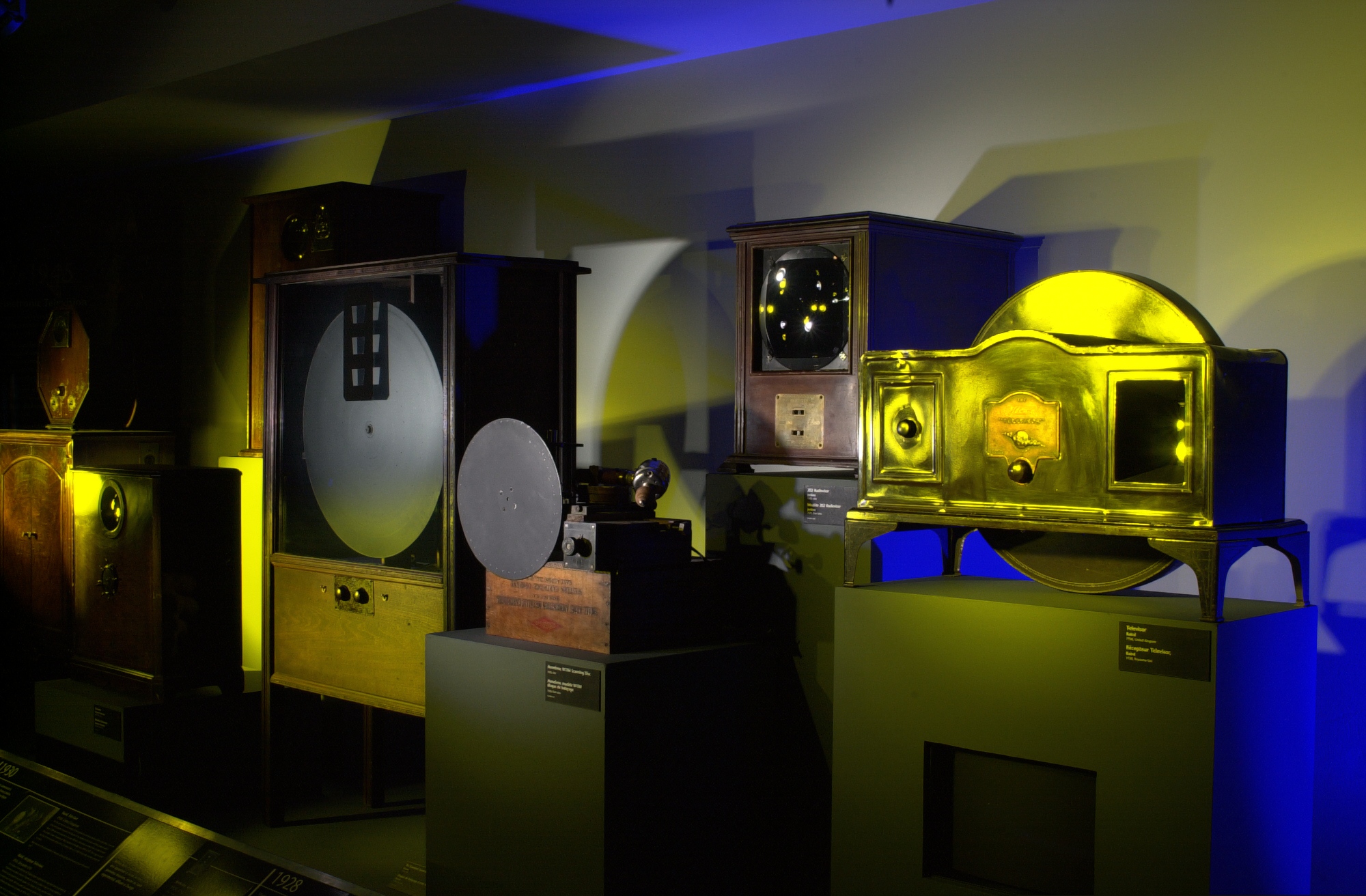
Study the work of Paul Nipkow, and his invention, the Nipkow disk, as well as early mechanical television.
Here is a picture of some early television sets that used the spinning
disk principle:
--Photograph by S. Mann, 2000 November 3rd, Toronto, Ontario, Canada, Nikon D1.
You can do this by taking a piece of black cardboard and cutting a small hole in it, and moving it across the image, while making note of its position, e.g. (x,y) coordinates, together with the amount of light received for each (x,y) coordinate. This method makes it easy to capture real-world scenes.
Another way to do it is to write a computer program that blacks out all but a small region, and moves a virtual mask around the image, and for each area of the image, you measure the amount of light present.
You can do this manually with pencil and paper for example, writing down each (x,y,q) triplet, and then enter the data later to generate the image, or you can automate the process. For example, you can display each region of the image on a computer automatically while digitizing the input from your photodiode. To digitize the input from your photodiode, you can use something like an Arduino or other microcontroller that has an analog input, to capture analog values into your computer while it displays regions of the image.
There is a photo contest for best picture taken by your 1-pixel camera!
Consider the response function, f, you would like to portray your final result on. For example, if you capture a real-world scene, you will have an image array in lightspace, q, and you may want to convert it to imagespace, f(q) so that it will look good in print or display media. Consider, for example, finding a suitable response function, f, to render your final image. A typical response function will be shaped like a square root function or something similar.
For this purpose we have a number of Muse brain-sensing headbands manufactured by InteraXon that can be signed out to students. You can use any of a wide variety of software available. We also have source code for direct "hacking" of the Muse. Talk to the TA Danson for access to it if you wish. There are also a number of online tools for reading Muse data.
Alternatively you can use other brain-sensing headbands such as Neurosky, or you can also build your own brain-sensing device and use a simple lock-in amplifier.
Marking (Part A):
Fun additional reading for Part B: The Human Eye as a Camera.
If you decide to do Part B, consider entering your brain photo into the photo contest!