EYEGLASS HEADS UP DISPLAY
H. W. Upton and J. R. Goodman
Bell Helicopter Textron
Fort Worth, TX
Abstract - A micro-heads-up display (u-HUD) that is worn like conventional eyeglasses is described. It uses a miniature optical system that presents an image at virtual infinity wherever the wearer looks. A miniature fiber-optics generator that presents a microcomputercontrolled raster display with 128 x 128 element resolution is also described. The details of fabrication of the 128-element LED array and the coupling of the scanning fibers are discussed. The application of the display for a helicopter-pilot heads-up-display (HUD) and as an aid for the deaf is also presented.
I. INTRODUCTION
A miniature wearable heads-up display, referred to as a Micro- HUD (u-HUD), has been developed that permits the wearer to see information superimposed in his field of view wherever he looks. The concept uses a miniature reflecting mirror positioned close to the eye to reflect the displayed image. The display has application where low cost and light weight are important, and especially for man-portable systems. The display has been used as a lip reading aid for the deaf and as a HUD for helicopter pilots' use for night flying. The display can present alphanumeric information or dynamic symbology such as a pitch roll bar.
The image is generated by a miniature display generator, in the bow of the glasses, which uses a vibrating fiber-optic ribbon attached to a linear light emitting diode (LED) array. A micro- processor pulses the diodes synchronously with the vibration to create dynamic symbols on the plane formed by the ends of the vibrating fibers.
II. DESIGN CONSIDERATIONS
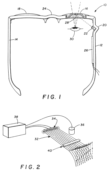
The u-HUD uses a reflecting mirror, mounted in front of the eye on an ordinary spectacle lens. The approximately l-mm-diameter mirror reflects the image via a folding mirror from a small image generator mounted in the spectacle bow (see Fig. 1). The wearer sees a virtual image superimposed on the background he is viewing. Figure 2 shows a horizon line and numeric information such as would be used by a helicopter pilot. The numerics can represent such flight parameters as altitude, airspeed, and heading. The pilot sees the image in whatever direction he looks, in contrast to a conventional fixed HUD where he must look directly forward to see the image.
Information presented in a fixed location, such as alphanumerics or dot patterns, can be generated by fixed LEDs which are switched on as required. A raster capability is necessary to generate moving symbols such as moving horizon lines or other dynamic symbols commonly used in aircraft HUDs. The generation of such a raster is discussed below.
The display has also been used as a lip-reading aid for the deaf. For this application, shown in Figure 1, a wearable speech analyzer extracts various features from a speaker's voice and the wearer sees a colored pattern representing the speech features superimposed on the speaker's lips.
III. - OPTICAL SYSTEM
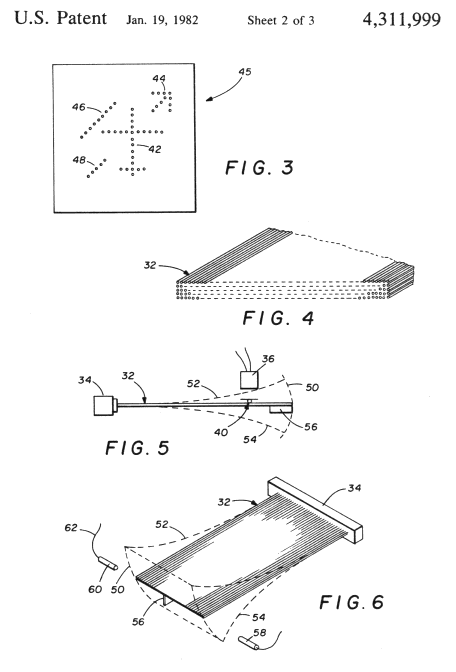
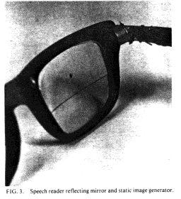
Two optical designs have been used with the u-HUD. One optical system uses a small concave reflecting mirror (see Fig. 3). If the front surface mirror is designed to focus on the image, an in- focus virtual image appears centered in the field of view. The mirror can be close enough to the eye so that a l-mm-diameter mirror will subtend 7-10 degrees in the wearer's field of view. The mirror itself is completely out of focus and is basically invisible to the viewer. The almost constant saccadic and nystagmic motions at the eye may also contribute to the mirror's invisibility.' In night flying applications, where the eye is at least partially dark adapted, a slightly larger mirror can be used that will give up to 15_ field of view without interferring with direct vision. Despite off-axis aberations and distortion, a simple spherical reflector allows good discrimination of numerical and moving line-type symbols commonly used in aircraft instrument displays. An aspheric reflector would be used for higher resolution imagery.
The second type of optical system that has been tested uses a flat reflecting mirror in front of the eye. A small refractive lens placed between the image generator and the mirror collimates the generated image. This on-axis optical system could be used to resolve a pictorial image of television quality.
IV. IMAGE GENERATOR
Dynamic information such as a moving horizon line for controlling the altitude of an aircraft or guidance information for approach and landing must be generated at the image plane which, in the present design, is 1/4 in.2. For showing line-type symbols such as are used in a pilot's HUD, it is necessary to have enough resolution so that the symbols can be resolved and they must move with a smooth motion.
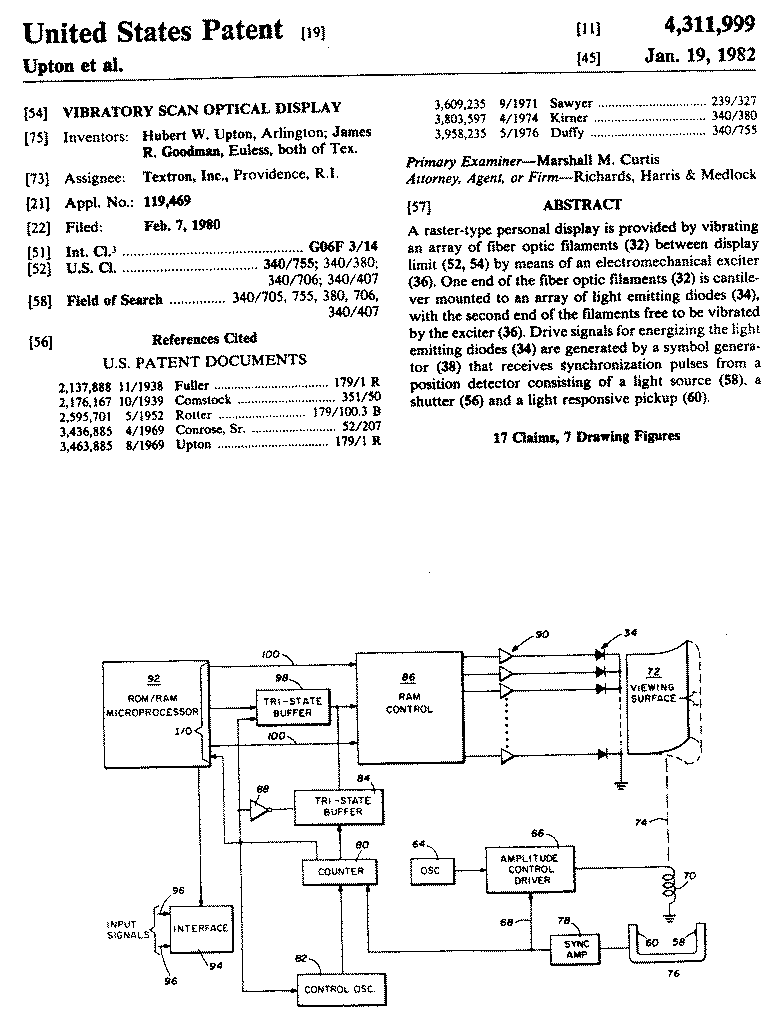
The concept for generating the dynamic image is shown in Fig. 4. Each diode of a LED array has a glass optical fiber attached so that the light appears at the end of the fiber. The fibers form a flexible ribbon which can be vibrated vertically. The glass ribbon has a high Q and a very stable resonant frequency which can be tuned to a frequency above the flicker frequency of the eye. By
Proceedings of the SID, Vol. 23/2, 1982 77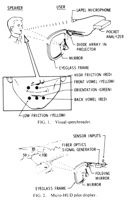
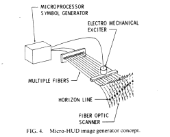
flashing the diodes synchronously with the vibration, dynamic images are formed in the image plane formed by the fiber ends. The upper and lower 15% of the scan are not used because of nonlinear motion. The central portion where the fiber velocity is nearly linear is used for the display. Since the nonlinear portion of the scan is repeatable, the microcomputer which is used to generate the display could be programmed to linearize the image.
The vibrating scanning of the fiber ribbon is achieved by the periodic magnetic attraction of a small magnetic strip which is attached to the ribbon. The magnetic strip is attracted by the electromagnetic (EM) coil which is pulsed at the desired frequency. The actual drive potential to the coil is controlled in a closed-loop configuration in order to precisely regulate the amplitude of the vibrating fiber during each cycle of the vibration. The feedback sensing is accomplished by using an IR LED and a phototransistor as a custom-made interrupter module. The vibrating fiber provides the optical interruption, and simultaneously provides the- synchronization necessary for image stabilization.
In one system presently being designed for the U.S. Marines, a special LED linear array has been fabricated with 128-0.001-in. GaAsP diodes on 0.002-in. centers. The array is made in sections of 16 diodes. Eight of the sections are then aligned on a substrate to make the 128-element array. A glass optical fiber is mated to each diode. The mating is accomplished by matching the fiber position with a phototemplate of the array. The fibers are then encased in a Kaptan cover to make a ribbon in which the fiber matches the array. The matching ribbon is then bonded to the array. Galileo Electro Optics Corporation produces the fiber optic ribbon and ITAC, Inc. produces the array and mates the optics.
The 128-element array is multiplexed in a 16 x 8 pattern to reduce the number of electrical connections required to 24. ITT-Cannon microconnectors with 0.025-mil pin spacing are used to bring out the wire leads. The entire module, including connectors to which the 0.55-in.-long fiber ribbon is attached, is 0.37S x 0.30 x 0.2S in. An early full-scale working model of the fiber-optic scanner is shown in Fig. 5. The small ferrite bar is attached to the fiber-optics ribbon. The electromagnetic coil is positioned directly under the bar and is pulsed to excite the ribbon into vibration. A tuning weight is added near the tip of the
78 Upton and Goodman/Eyeglass Heads-Up Display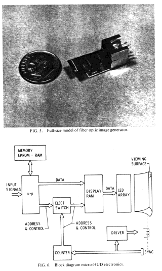
ribbon to tune the ribbon to resonate at the desired frequency. The bending of the glass fibers is below the stress level in which fatigue damage would be introduced. The scanner ribbon should thus have a long life. To date, one model has accumulated several thousand hours with no detectable degradation.
The 128-line display is pulsed 128 times each vertical scan to create a 128 x 128 pixel display. The present display is pulsed only during the down sweep of each cycle. Since the LEDs are multiplexed, the eight 16-element segments must be successively pulsed eight times during the time the ribbon passes each row of dots. This works out to a pulse width of approximately 4 usec. The worst case duty cycle of each diode is 12.5% (assuming a full vertical row of dots is displayed). With the present LEDs, at that duty cycle, each pulse can have 0.5 A of current per diode. This current level gives an average intensity of 500 uCd. This should be adequate to give a good contrast image against the background for which the display is intended. This is a night mission where the u-HUD image will be superimposed over the background of a night vision goggle image.
V. ELECTRONICS GENERATOR
The display symbology is generated by the programmed 8085 microprocessor as shown in Fig. 6. The program is stored in eraseable programmable read-only memory (EPROM). Input signals are conditioned, digitized, and latched by the microprocessor and the data are stored in microprocessor random access memory (RAM) where all
Proceedings of the SID, Vol. 23/2, 1982 79
inputs and outputs are memory mapped for maximum processing speed and ease of data manipulation. The points required to generate the desired symbology are then calculated and loaded into the display RAM under interrupt control. The display RAM is addressed and controlled to drive the display, on each scan cycle, by a synchronizing signal taken from the scanner since the microprocessor is not fast enough to output data to the display in "real time." The electronic switch connects the address and control lines going to the display RAM to the counter for the output portion of the display cycle and connects the lines to the microprocessor for updating the display RAM during the retrace portion of the cycle. Since the display for the pilot HUD application has relatively few "on" pixels, the display refresh time is improved by simply erasing (loading 0's to the display RAM) only for the previously illuminated pixels instead of the entire display. Since the address of each illuminated pixel is known, this is readily accomplished.
Vl. APPLICATIONS
The u-HUD has many potential applications. It is presently being used in the experimental visual speechreader for the deaf where a wearable speech analyzer extracts certain features from speech. The u-HUD is also being evaluated in a U.S. Army program to add helicopter altitude, heading, and airspeed to night-vision goggles for helicopter night flight. Promising results have been obtained. A system is under development for the U.S. Marines to present attitude, altitude, heading airspeed turn and bank, and warning information to a pilot flying with night-vision goggles. The system is especially applicable to small aircraft and helicopter displays where light weight and low cost are important. It has application for aid to the deaf and other handicapped persons as well as other man- portable system applications or for personal messages or entertainment use.
ACKNOWLEDGEMENTS
REFERENCES
